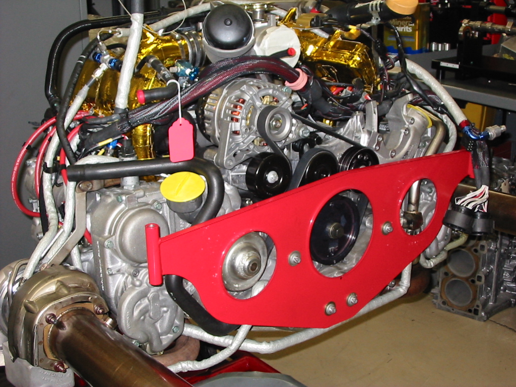
Porsche 996 and 997 Turbo Cylinder Head Sealing
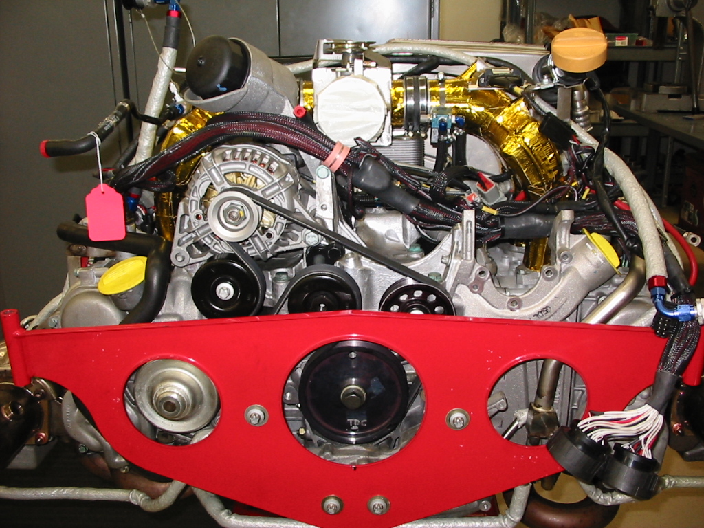
The aftermarket is now building these engines with performance levels well above the original level sold by Porsche. In some cases, power levels have past 1000BHP. We have seen engines and parts that have failed due to head sealing and often the fault is considered the head studs failing to hold the head down to the cylinder. In a lot of cases this is not the only cause and many other factors add to the failure.
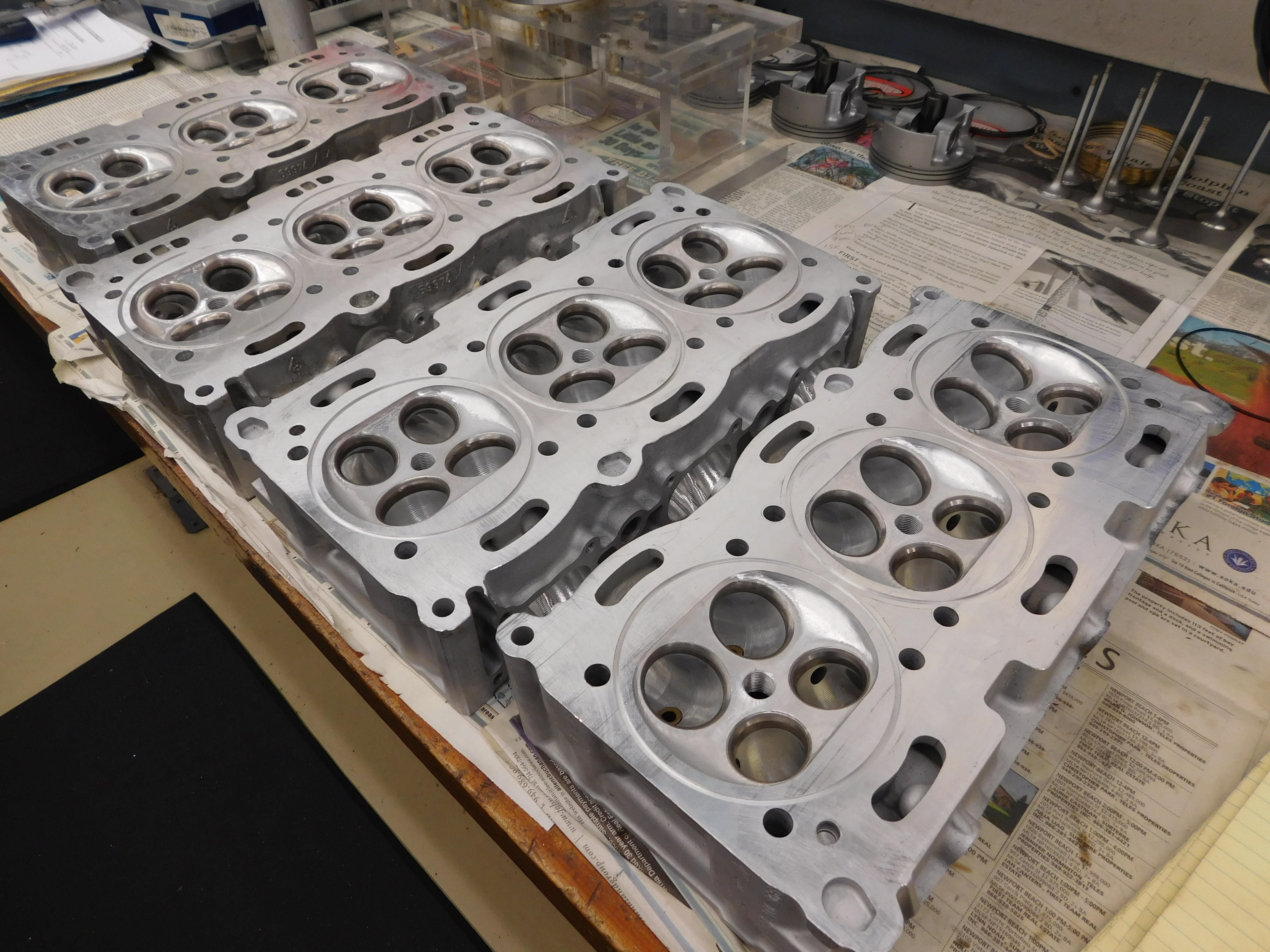
The first thing that should be known is the 996 Turbo Head went through an upgrade where the casting was beefed up to stop the cracking that occurred in some 996 engines. The heads at fault were cast in France and the new “heavier” head were cast in Germany. So, the first thing you should look for is the “Made in Country” before doing any performance upgrades. Not all heads cracked, but if you are going to push the engine beyond its intended performance level I suggest you consider changing to German made heads.
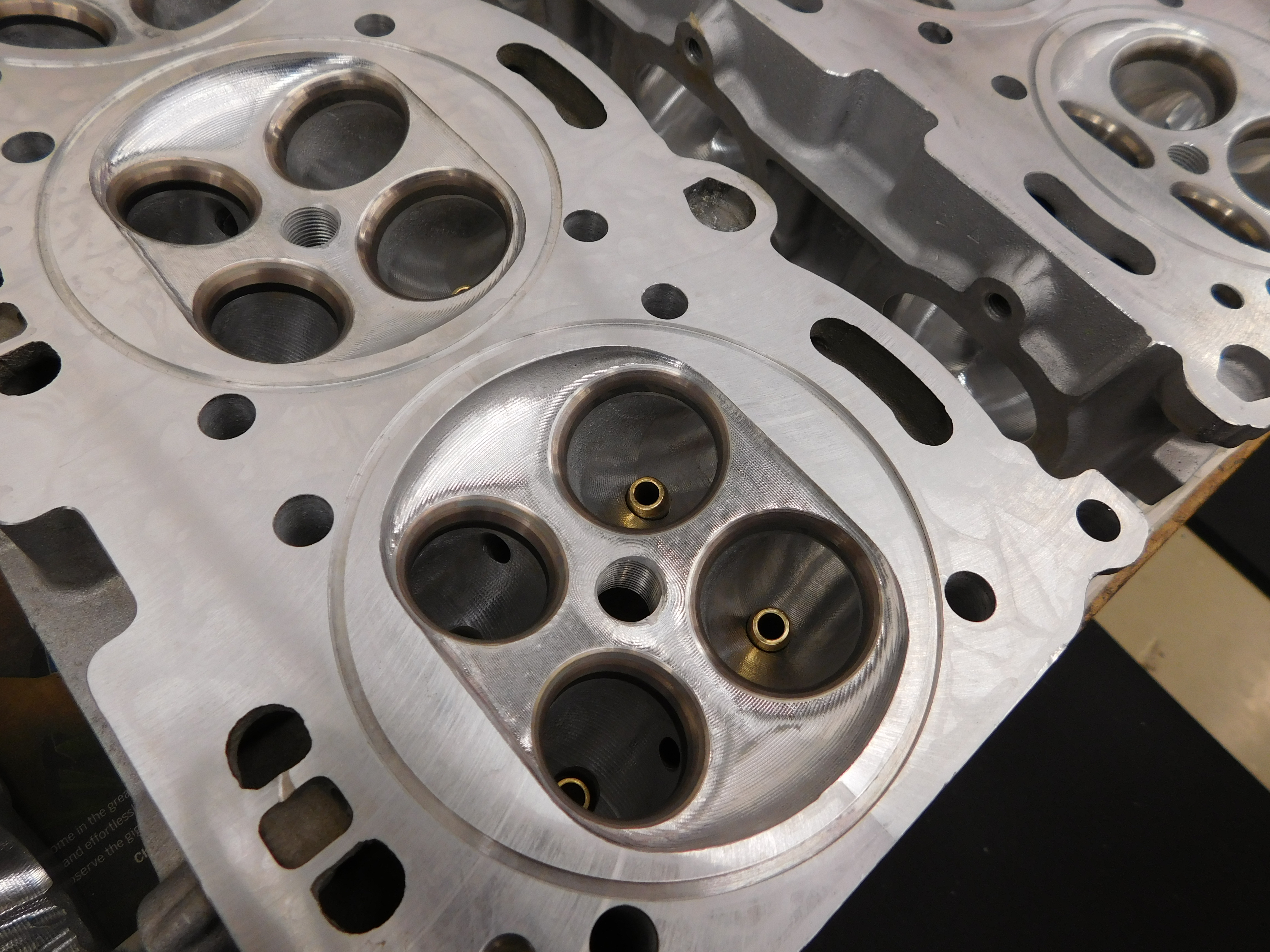
Then make sure the valve guides are in good shape and all the normal cylinder head rebuilding processes are done. Make sure the company doing this work know these engines and know what is required in building high performance cylinder heads. Make sure they do this work in house so you can control the quality and actually get what you are promised. Be sure you know the limits of the parts used in the build.
These engines use a hydraulic cam follower. The intake follower should be changed and Performance Developments uses a flat, solid follower on both the intake and exhaust valves. We do this for both a performance and reliability reason and add the acceleration into the cam profile. Remember the vale lift is the same whether you use a radius follower or flat.
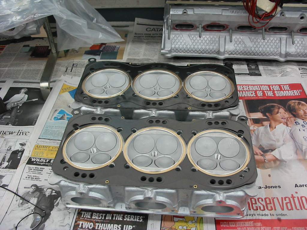
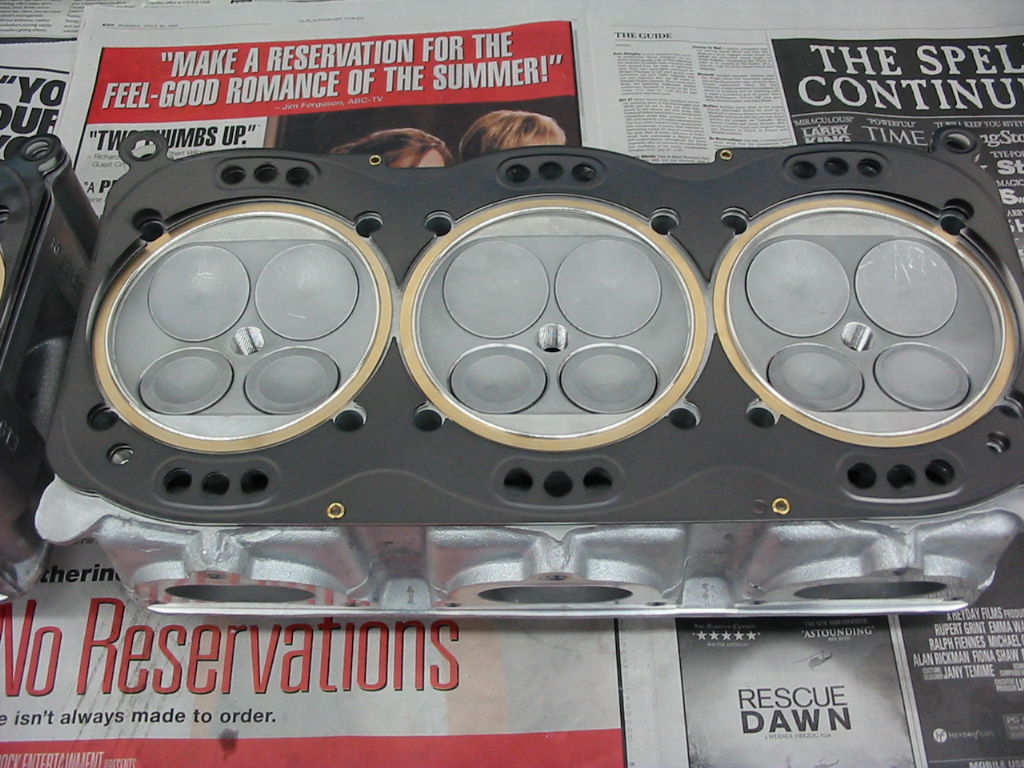
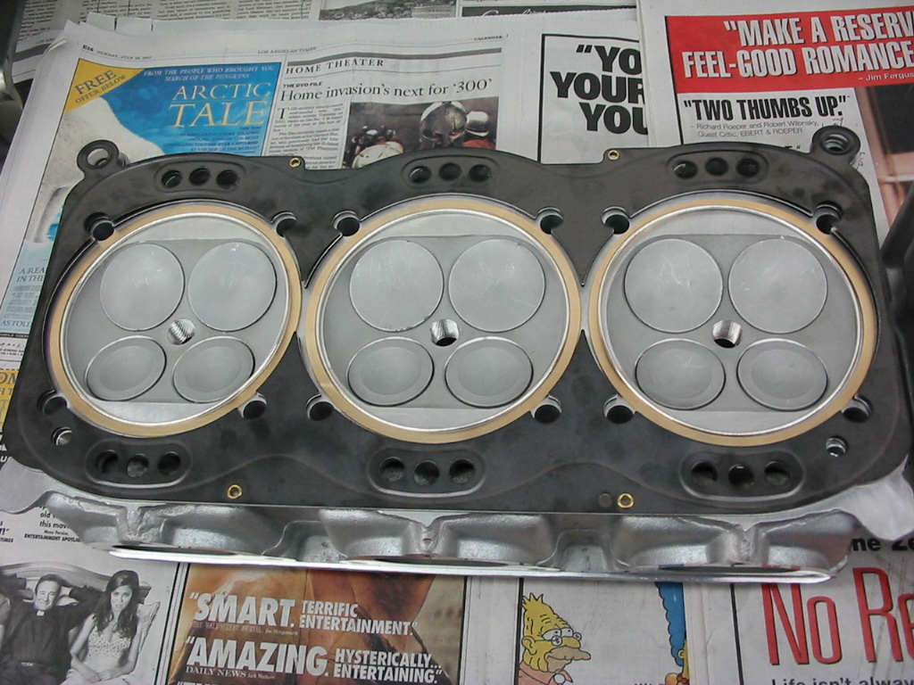
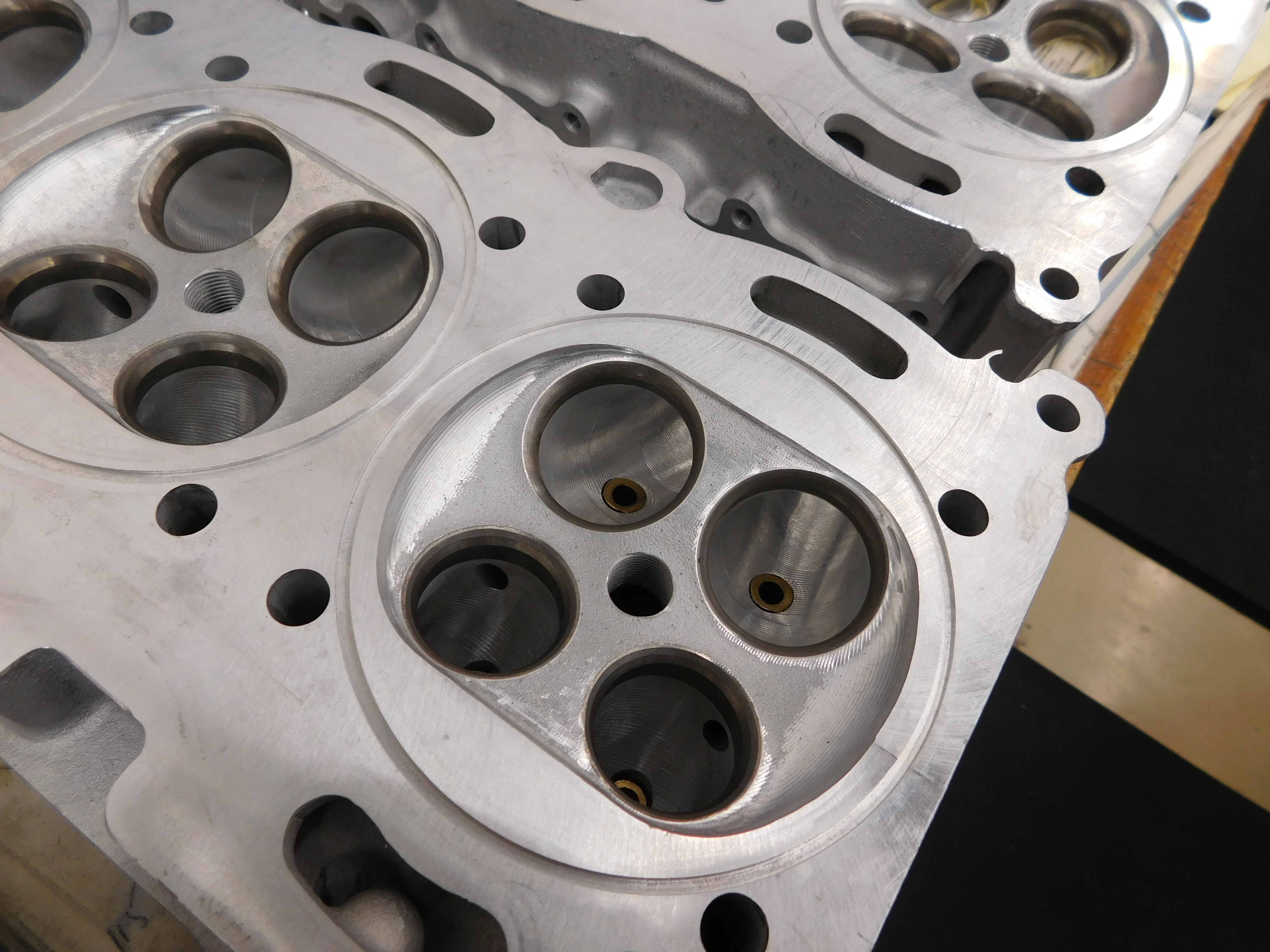
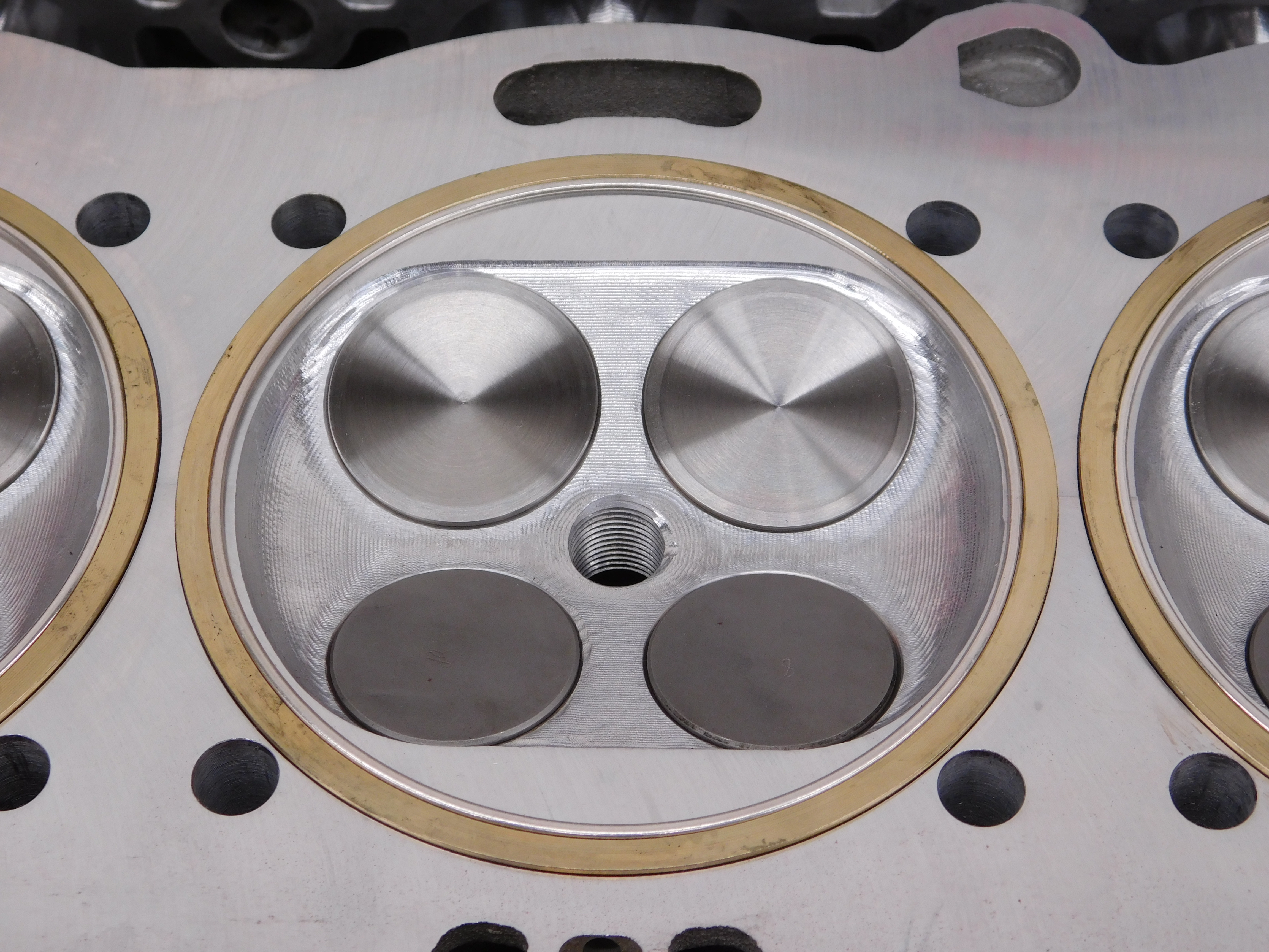
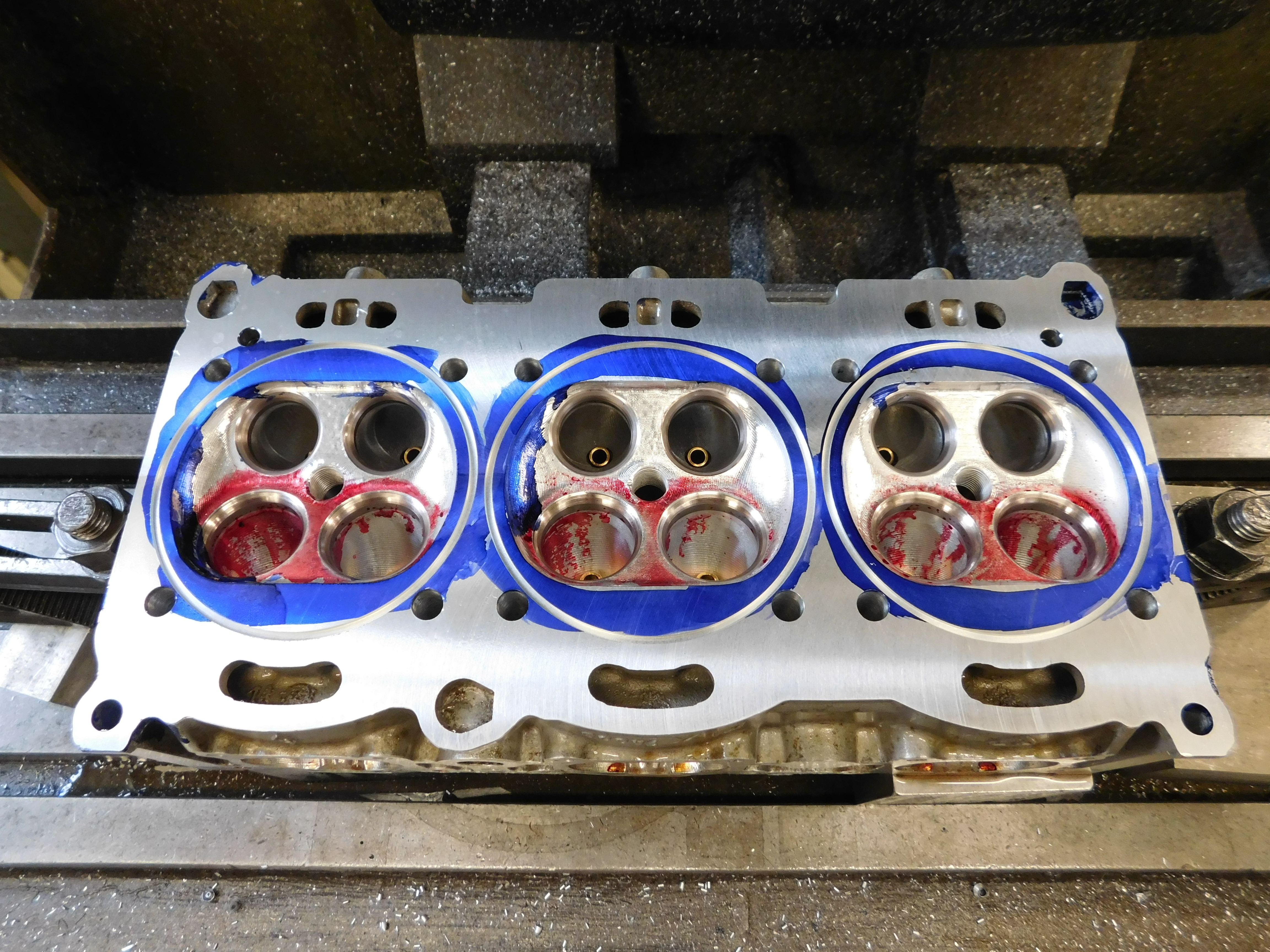
The other major issue is the head sealing. So much has been written about the cause of this being the inability of the head stud to hold the heads to the cylinders. Sure, the head stud play a critical part in this, but the gasket and its ability to seal also plays a huge part as well. Performance Developments was the first to develop a 5 layer MLS gasket for these engines. Our system uses 3 parts to the sealing system. The 5 layer MLS gasket, a gas filled crushable ring and its back-up ring. The gasket seals only the water and the oil passages between the cylinder housing and the head. The gas ring seals the combustion chamber. Copies of our system have eliminated the back-up ring and use only the sealing ring and head gasket. However, we feel that the back-up ring plays a very important role in the sealing system. It supports the outer diameter of the gas ring, and also sets the crush of the gas ring at the gas ring.
These engines have a 90.00mm head stud separation and between the head studs at each cylinder are the water passages. Dead center in fact 90° to the crankshaft. As the head is pulled at each head stud, the head actually bows up very slightly. This is normal with almost all heads as you are pulling the head down at the stud and expecting this same clamping force to be equal over the whole length of the head. It never is, so any added sealing you can add between the head studs is always a good idea.
The gas ring is crushed some 0.020” when the head is bolted down. The back-up ring not only limits the crush but also directs any deformation inwards towards the cylinder and not outwards towards the head gasket. In the copied system, it is always hoped that this deformation if outwards does not interfere with the sealing embossment of the head gasket. If it were, you would not know until you ran the engine and pressurized the cylinder under boost. The 3-piece system ensures that the back-up ring separates the gas ring and the head gasket, ensuring that the sealing is not compromised. We believe that you use every opportunity to engineer a solution and leave nothing for chance.
The other very important area to look at is the head washer platform in the cylinder head. The studs are 10.00mm or in some cases 12.0mm with the through holes in the head larger for clearance. Under clamping loads, the heads material surrounding the stud collapses inwards around the stud, resulting in a washer platform not flat but tipped inwards. The washer now does not sit flat and contacts the head on its outer edges. When the nut is tightened and the stud stretched the washer also buckles and the nut does not set well against the washer. This smaller contact surface changes the friction a lot and often the combination of the head not being flat from previous clamping or the head collapsing at this time along with the nut and washer issues, the head clamping loads at each head stud can be different. If you use a small amount of torque to seat the head when assembling the engine and then go back in sequence and add more or use an angle method, without first going back over each nut again in the seating sequence I can guarantee different clamping loads. The center nuts will always loosen up each time you go through all of the tightening procedures.
This may be getting off track some, but it should be used as a guide. It is hoped that you understand that there are many factors that are in play here to make sure you have a safe running engine.
