Porsche 6 Cylinder Harmonic Engine Failure
The Silent Killer
This is a term I am sure you have heard before, but probably not heard it used in the context of engines. Engine failures are not uncommon; all of us have either been the victim of a failure or know someone who has. Most often it is your typical failure, one we have seen or heard of before. Recently, failures that result from a different kind of cause are becoming more common. The Porsche GT3 engine has had quite a few harmonic failures as evidenced by the volume of emails I have received and our own unfortunate experiences. Just to put this in context, all engines suffer from this phenomenon.
Engines create a continual series of vibrations known as harmonics. Each time the engine ignites the fuel mixture and there is combustion, the forces from these combustion’s act upon the crankshaft. The forces generated from these combustion’s force the pistons downward which, in turn, rotate the crankshaft. This is known as tangential torques. The rotating and reciprocating masses create torque pulses within the crankshaft each time it rotates.
The Porsche GT3 engine seems to be having its fair share of vibrational failures. We have seen crank pulley bolts and flywheels come loose, cam actuators come apart and in our own particular case we had an engine that broke the scavenge gears inside the oil pump. I know of other GT3 engines that have had similar failures. These failures are not new to the Porsche Boxer engine.

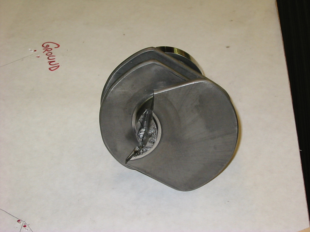
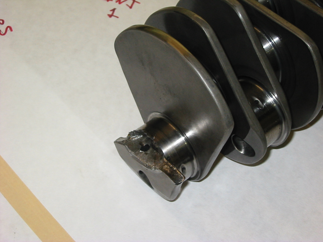
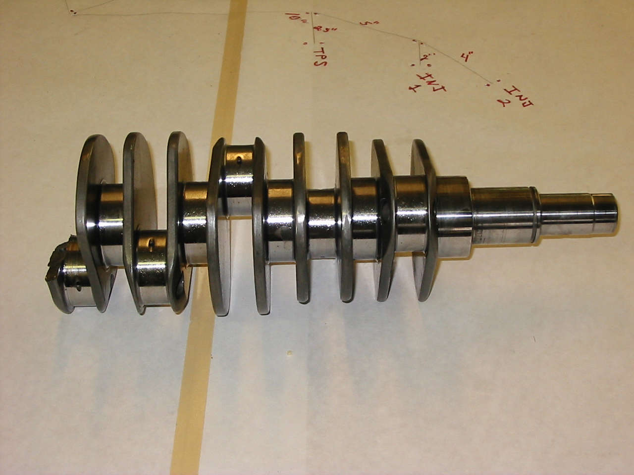
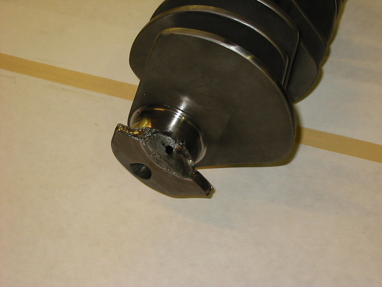
In another situation the crankshaft actually broke.

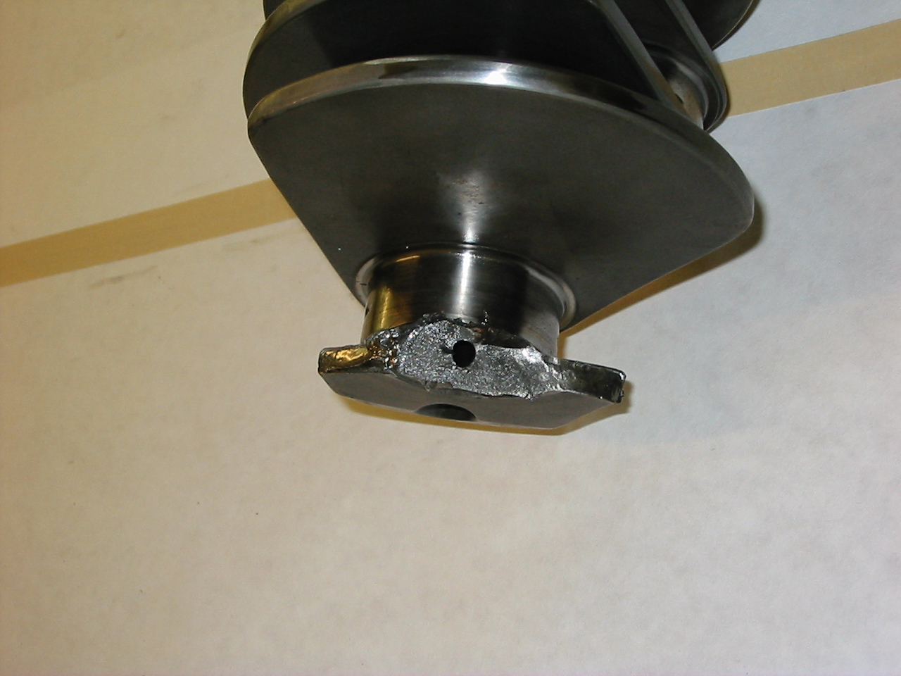
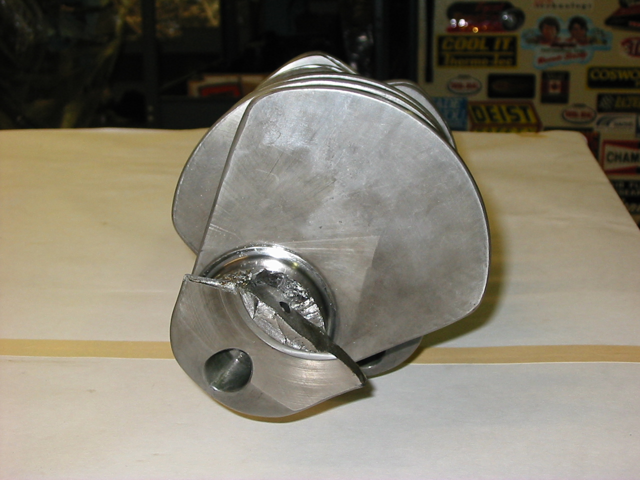

Harmonics are not new. For years the Porsche Boxer engine has been thought of as a neutrally balanced engine with each pair of opposite pistons always in the same position and the forces are counter balanced or cancelled out. Not so. As engine internals have become lighter and lighter to meet mileage requirements the issue of balance and harmonics has become more real.
The Porsche engine in the 962C race car had huge issues with harmonics. In the US this engines displacement was 3.0L or 3.2L engine with 70.40mm or 74.40mm stroke using a single lightweight flywheel and a small steel crankshaft pulley to drive the alternator. We saw complete crankshaft failures where the crank would break into two pieces and a lot of camshaft drive failures. The cam drives in these engines were all gear driven. They would “vibrate” so much that bushings in the gear housings would rotate and the roller bearings would starve of oil, seize on the gear shafts, the cams would stop turning and the rotating parts of the engine would often saw the engine in half. Cause = Harmonics. Result = Engine Completely Destroyed. Solution = Custom Built Damper to Eliminate Harmonics. Very hard to diagnose the cause when there is little left to inspect. This was a silent killer.
Recent failures seen in the late model Porsche GT3 and Turbo engines are not a Porsche problem, they are an engine problem. Porsche have suggested that these issues have resulted from modifications of the original spec’ed engines. Their Technical bulletin (GT3 Engine: Flywheel and Pulley) speaks directly to this matter. However, the removal of the dual mass flywheel is not the cause. The springs inside the flywheel and the mass of the flywheel have some dampening effect, but it needs to be understood that dual mass flywheels are not harmonic dampers. Dual mass flywheels are used to stop transmission failures, not dampen engine produced harmonics. The earlier 996 GT3 engines came with a rubber “tuned” damper similar to the one used on the earlier 993 engine. Why this was removed from later engines mystifies me when Porsche must have known about the harmonic issue. Regardless, all of the GT3 engines have had engine failure problems caused by the internal harmonics with either flywheel fitted. Even the Turbo engines have had their share. Like a lot of the GT3 failures, the real cause has not been identified and only the result has been addressed.
I have read where the camshaft adjusting actuators are poorly designed and therefore are the cause of the retaining screws backing out, not so. This type of thinking and diagnosis stops at the visual result but does not consider nor understand the cause; hence the “Silent Killer” title. Although adding further loctite to the screws cannot hurt, this doesn’t solve the problem. It can just move the problem down the chain. To loosen these bolts the vibration is transferred from the crankshaft into the 1st motion shaft or Intermediate shaft as it is known in the Porsche world. This shaft drives the chains that drive the camshafts.
This same intermediate shaft drives the oil pump and the same vibrations that go up through the chains go into the oil pump. The pump gears are made of sintered metal, very brittle and weak material. In their normal function without the inducement of harmonics the scavenge gears are loaded and unloaded on each rotation often scavenging air then oil then air again. The unloading effect causes them to bang backwards and forwards. Now add in the high frequency vibration to a gear made of very brittle material. The keyway groove machined into these gears has very sharp square corners at the root of the adjacent gear tooth. Think you fix one area and the problem moves to the next weakest part!
I have been asked why Cup or RSR race engines do not suffer from these same failures. They do, but with some exceptions. First, these engines do not have electronic variable adjustable camshafts so their camshafts have fixed timing. Second, their typical operating RPM range is 5500 and above. The failures seen in the street engines typically happen after periods of low speed driving. Racing these street engines does bring into play other issues, but the harmonic range that causes most of the failures is at lower engine speeds. Continual high speed operation of these race engines above their safety limit has resulted in complete crankshaft failures, just as we have seen in the earlier 962C engines.
I have included a paper written by William C Sisc explaining, in technical terms, the problem of harmonics and the use of dampers to counter these damaging forces.
|
Crankshaft Torsion and Dampers Torsion — The hidden problem with the crank system — and why it needs a damper o First — Special words to know § Frequency, RPM, Orders, Modes, Nodes and Inertia § Frequency — is how many things happen in a period of TIME = (cycles/second – called Hertz and abbreviated (Hz)). The crank natural frequencies are defined this way and are constants; they do not change with RPM. § RPM — is revolutions of the crank per minute § Orders — are defined as events per crank revolution. Because of this, their frequency is variable and goes up and down with RPM. Also, because the orders are in nice neat increments to each other, they tend to be confused with harmonics. § This is where the term Harmonic Damper creeps in, but is not quite technically correct. Harmonic is normally a time-based term (usually multiples of a base frequency) and orders are an event-based term. The damper is tuned to ONE frequency and damps the various orders as they excite the SAME frequency in the crank at different RPM. § Mode — describes a pattern of twist in the crank. Basically it describes the number of places the twisting motion changes direction from clockwise to counter clockwise. § Node — the name of the places where the crank vibration motion is zero as the motion changes from one direction to the other. (i.e. Second Mode motion has 2 Nodes) § Inertia — (also known as the polar moment of inertia) is the tendency of a mass to resist changes in rotation speed (RPM). It is mathematically the mass times the square of the distance of the CG of the mass from its center of rotation (m x r2). It is different from weight because the radius2 factor makes it very sensitive to the diameter of the part. A thin flywheel has a much higher inertia than a long, small shaft of the same weight. o Torsion in the system. Where it comes from — why it’s a problem § Torsional vibration is twisting of the crank from one end to the other. It happens at fairly high frequencies (usually 250-400 Hz) and is driven by two different uneven torque pulses coming from the pistons. The angle of the twist is small, (up to perhaps 1.5-2.0 degrees in bad cases) but because of the high stiffness of the crank, it involves torques within the crank that are much higher than the torque that goes out the flywheel end to drive the car. The high frequency and high torques drive fatigue failures of the crank and high bearing wear as well as other side effects on things driven by the crank.
§ Combustion pressure torques — each cylinder delivers most its energy in about 100° of crank rotation, and only every other rev in 4 strokes. § Reciprocating component torques — each piston/rod applies a reversing torque twice/rev to accelerate/decelerate at TDC & BDC § The crank masses and stiffness between cylinders have a built-in torsional frequency that will “ring” in a torsional manner just like a tuning fork. Think of this system as a stack of little flywheels, one at each crankpin location with a torsion bar (the mains) connecting them. There are usually two different frequencies present in the operating range of the engine that have different patterns (Modes) of twist. § The first mode frequency has the whole front of the crank forward of the rear main twisting one way while the flywheel goes the other. This puts a dead spot (or Node) at the area of the rear main where the motion changes direction. This is also the point of highest stress and is usually where the crank breaks from a torsion-related problem. § The second mode adds another dead spot (Node) somewhere in the middle of the crank and has both the front part of the crank and the flywheel going one way while the middle goes the other. Because the sections between the nodes are shorter, with the same stiffness between them, the second mode frequency is higher than the first mode. § Both of these modes of vibration can occur together in the higher RPM ranges. § Torsional vibration peaks occur when a frequency component of the piston firing and reciprocating torques gets close to one of the built in frequencies of the crank. § When the inputs get close to a natural frequency, the system goes resonant and the twist angle gets magnified about 6-10 times the normal amount in a very sharp “peak” that is only a few-hundred RPM wide. § This magnified twist is what does the damage in crank stress and bearing wear. It is dangerous in that it builds up fatigue stress cycles very quickly because it is such a high frequency. The vibratory torques at these resonant peaks can get much higher than the drive torque going out the flywheel. § The first natural frequency of typical V8 & V6s is usually in the 300-450 cycles/second range. § These vibration peaks happen at several different RPM points in the RPM range of the engine. Not only are the firing and inertia forces driving at different basic orders (1/2 /rev and 2/rev per piston for a 4 stroke), but also the distorted shapes of those torque pulses contain multiple torque components creating the other Orders. § The multiples in the shape of the torque pulses are called order content. It is sinusoidal pieces of the torque pulse that are related to how many times/rev each piece happens. (1/2 – 1 – 1 1/2 – 2, etc.) § Some orders (the lower ones) are stronger than others and that is determined by the shape of the torque pulse and the firing order of the engine § The end result is that each natural frequency of the crank can get driven into resonant peaks by several of these orders as the engine runs through the rev range. There are usually 3-4 big peaks and lots of smaller ones. § The good news is that the peaks in an engine without a damper are usually ALL THE SAME FREQUENCY unless the engine revs very high. This is normally the first mode frequency of 300-450 Hz as mentioned above. § The second mode frequency of the crank is usually 1.5-1.8 time higher than the first mode and is usually high enough that is does not have peaks in the normal rev range. § The exceptions to this are long engines (inline 6s and 8s) and or engines with unusually low natural frequencies (flexible cranks or very heavy reciprocating weights — think marine ship engines) § A second exception, are engines with very high RPM ranges. (Think Indy or Formula 1 types) § (A typical torsion map of an automotive V8 engine is shown toward the end of this page.) o How the damper works to reduce crank torsion § In its simplest form, the damper is just another mass (the inertia ring) and a spring (the rubber strip) tuned to a single frequency. This is added to the crank system at the end with the most torsional motion; (the end opposite the flywheel). The damper motion always lags behind the motion of the crank and imparts a lagging torque to the motion of the crank vibration and also absorbs some energy from the crank motion as the rubber strip flexes back and forth. § The damper is tuned to go into resonance at a frequency between the two main crank frequencies. (Although those two frequencies have lowered a bit due to the added mass of the damper on the front of the crank system.) The crank twist is reduced by the lagging damper torque and energy absorption, and the damper ring’s twist motion on the rubber increases in the bargain. The trade-off is that the damper becomes the highly stressed part instead of the crank. § The tuning frequency of an OEM damper is typically specified with a tolerance of about +/- 8% at a temperature of 150°F and a motion input similar to the operating crank vibration (+/- 0.1° applied to the hub). It must be done this way because the temperature and the amount of motion in the rubber both affect the dampers’ frequency. 2. Damper Characteristics o What things make any difference to the dynamics? § The crank, looking out at the damper fastened to its nose, can only really “see” 5 things. 1. The size (inertia value) of the damper ring 2. The tuned frequency of the damper (whether it is reasonably correct or not) 3. The damping built into the rubber composition (high to low) 4. The parasitic inertia of the damper hub. (the hub becomes an added inertia to the crank system and more hub only makes the damper’s job more difficult) 5. The weight of the damper. This is most important when sideways bending of the crank nose is considered. § How these 5 things happen is “invisible” to the crank. It does not care about cast vs. billet metals or what shape the damper is. All the other details of the damper are aimed at secondary things like driving accessories, low cost, light overall weight etc. o Balance — The damper is no more of a “balancer” than an ordinary belt pulley would be. Nothing about the resonant motion of the inertia ring /rubber construction does anything for balance. The damper is balanced to a neutral specification for internally balanced cranks and may incorporate a bobweight for externally balanced cranks. BUT, the balance is a completely separate function from the torsion control. o SFI Certification — The widely advertised SFI certification is a safety issue that has nothing to do with the damper’s ability to control torsion. SFI basically specifies wrought (billet type) materials and an assembly method that traps the inertia ring from coming off the hub should the rubber fail. The SFI proof test is a high-speed spin test (with no torsion input) for a certain amount of time with the damper mounted, as it would be on the engine. While this certifies that the damper will not burst from centrifugal force, it says nothing about whether the damper was properly sized and tuned for a particular engine. o Viscous Dampers § The viscous type damper is a popular alternative to the rubber element type and operates in a slightly different manner. § The inertia ring is completely enclosed in the housing and surrounded with a very thin layer of high viscosity fluid. (usually silicone based) § The inertia ring is free to rotate (back and forth), and it too lags the crank torsional motion and applies a lagging torque to the crank nose. The ring motion running back and forth in the housing shears the fluid and the fluid absorbs energy from the crank motion similar to the way a rubber strip does as it flexes. § The biggest difference is that the inertia ring does not go resonant at any frequency and is thus not “tuned” like the rubber damper. § There is, however, a best dynamic stiffness where the damper works best. This is controlled by the viscosity of the fluid and the clearance between the housing and the inertia ring. § These dampers tend to be less frequency sensitive and have a very long life when properly designed. Their ability to absorb large amounts of energy makes them the best choice when the engine gets big. They are the best choice for truck and marine diesels. § They do have limits and some downside for the smaller engines. § They are heavier than a rubber damper for a given capability, § The housing inertia is all parasitic “hub” § The ring’s effective inertia is only half of its measured inertia. The physics of the system places half the inertia to the active side controlling vibration and half to the hub side as even more parasitic inertia. § The life of the viscous fluid is not infinite. Under prolonged heat and shear loading it can break down chemically and leave the ring too “free”. It can also get contaminated with bearing wear particles. The problem is there is no good way for the average user to detect this other than sawing the damper apart. The big dampers in ship engines have samples of the fluid taken periodically and an analysis is run to determine the condition of the fluid. The big dampers are take-apart rebuildable. § Another failure mode is that the bearing materials between the ring and housing can fail and the ring “locks up” solid to the housing. Then you have a really heavy dead weight pulley. Again, there is no easy way to detect this for the average user. § Third, the housing must not be dented via poor handling, the clearances inside are only in the 0.010 range and dents can “trap” the inertia ring and lock the damper. 3. Crank Variables o Common variables and the trends § Steel vs. Cast — The steel cranks will have frequencies a few % higher because of higher material stiffness (approximately 10 %) than an equivalent cast crank. § Stock vs. Stroker — Stroked cranks tend to have a little lower frequency because the crankpin/web areas are not as stiff. The main/crankpin overlap is less, and they have a little more weight (hence, rotating inertia) in the counterweights to balance the increased stroke. § Crank Pin Diameter – Crankpin diameters don’t tend to change the frequency as much because the lower stiffness is offset by lower inertias of the pin itself and the rod big end. Stresses however are generally higher. (smaller pin and less overlap) § Main Bearing Diameter — Larger mains increase the frequencies via higher torsional stiffness and vice versa. § Internal vs. External Balance — Internal balance generally means heavier counterweights overall and lowers frequency a bit. The bending stresses are generally better distributed. External balance is usually done to lighten the crank as the weight needed to get the end-to-end balance moment is moved as far as possible to the outer ends of the crank. § Heavy Metal Bobweights — Pretty much same effects as internal balance. § Light Pistons — This reduces the reciprocating torques and takes a little weight out of the bobweights. It makes more difference at the higher RPMs. § Short Rods/Long Rods — This has some effect on the shape of the reciprocating torque curves but not much effect on torsion overall. Again, more effect at very high RPM. 4. Other Rotating Group Parts o Heavy vs. Light Flywheels. Light flywheels lower the whole system inertia, move the high torsion stress point a little farther forward (away from the flywheel), raise the first mode frequency a bit, and sometimes allow a little smaller damper. They also allow more crank lugging motion which usually shows up as gear rattle in the transmission. (This is called “rigid body motion” in the torsion trade since the crank is just seeing RPM variation without twist) o Light vs. Heavy Pulleys. Heavy pulleys are just more parasitic inertia at the light end of the crank and make the damper’s job more difficult. They lower the frequency a bit but make the crank seem larger to the damper; i.e. a larger damper ring needed. o Blower Drives. Mechanical blower drives for Roots type blowers can actually help the damper by acting as more damping at the front of the crank. Mechanically driven blown engines generally are no worse, torsionally, than normally aspirated. Turbos usually are worse. o Dry Sump Drives. Not much effect other than some torque required to drive the pump. o Cam Chains. Cam chains can take a beating from the torsion peaks. Same for cam gear drives. The vibration motion tries to make the cam drive do the same motion and jerks the chain back and forth. If this motion gets through to the cam, it doesn’t help cam dynamics and can also show up in the spark scatter with cam driven distributors. o Spark Scatter. If the spark is taken off the front of the crank, the torsion motion is in the trigger wheel as well. The best place for the trigger wheel is near the rear of the crank where torsion motion is smallest. (guess where the OEM’s are putting their sensors now) o Transmission Gear Rattle. This is mostly caused by low frequency torque pulses (“rigid body motion”) in the crank at lower speeds when flywheel energy is low, although this motion usually persists out as far as 2000-3000 RPM. Aluminum flywheels make it worse for the obvious reason. These frequencies are way lower than the damper is designed for and the damper has virtually no effect on the gear rattle problem. Dual mass flywheels go after this problem. 5. The Damper/Crank-nose Connection o Dampers on any performance engine need to be fastened really tight to the crank nose. Most need the combination of a press fit plus a good tight crank bolt. The key has little torque capability by itself and will quickly fail if the press fit/clamp load cannot carry the damper and accessory drive torques. o The lagging torque generated by the damper when it is controlling one of the torsion peaks can easily be 200-300 ft. lb. and the torque from a big damper tuned high for a high RPM big block can get toward the 1,000 ft. lb. range. o It is not uncommon to see fretting at the back of the damper where it buts against the timing sprocket or crank shoulder. This only means the damper is actually slipping on its mount and cannot pass all the torque back to the crank. o Think of the key as nothing more than an indexing device for the timing marks or ignition wheel, it won’t keep the damper on by itself. o Short bolt/Long bolt § Putting a bigger diameter bolt into the crank nose might help hold the damper tight but may actually go the wrong way in the end. The bolt clamp load serves to pull the crank nose into the damper hub and leave the crank with a tension stress back at the end of the bolt threads or the back of the damper hub right at the end of the keyway region. All too often this can contribute to broken crank noses. § The best solution is to move the damper bolt threads back into the main or even the first crank web, put in a long high grade stud and tighten that to the maximum. This gives lots of bolt stretch for heat expansion compliance and leaves the crank nose neutral or in compression rather than tension. (Don’t do this without checking to see where the oil hole for the main is located) 6. Damper vs. Engine Application o The damper is tuned to give the best compromise of low torsion across the RPM range that the engine sees at high loads. That means that the intended use of the engine has a great affect on what the best damper/tuning will be. o OEM dampers are usually tuned to reduce torsion most in the low to mid range, where the engine spends 99% of its life. This may leave some higher torsion near redline, but very few production engines live their life there. This choice is also why some large, low- RPM V8’s got away with no damper at all. o Even modified street engines may be only a little different than OEM in their overall operating envelope when the time spent at various RPMs is considered. o Racing is another story. Crank system changes may alter the crank natural frequencies a bit (usually in the +/- 10%-15% range), but the real changes are in the operating envelope. o The usual problem is that the higher RPM ranges have both first and second mode frequencies present. The peaks of both can even overlap each other at the same RPM. Since the damper is only tuned to one frequency, the tuning may have to be compromised upward to do a better job on the high frequency second mode peaks. This is what drives the common rule of thumb “high performance dampers are tuned higher”. o It’s a common perception that higher RPM is a mandatory connection to higher tuning. Not really. The higher second mode was always there, the RPM window just moved upward enough to expose them and force the damper tuning to consider both frequencies. o Heat is the ultimate enemy of the rubber damper and the power absorbed (and heat generated) goes up with the square of the frequency. Thus, it doesn’t take too much upward shift in the tuning (40%) to double the heating tendency of the damper. Strain (the distance the rubber flexes back and forth) is next most important and the rubber must have adequate flex life capability to cope with this. Rubber compound technology is everything here. o The OEM’s spend a lot of time developing the rubber for heat and flex resistance. Lab life tests can run from hundreds to thousands of hours. Traditionally, they have used at least 5 different rubber compound “families”. They are, in rubber terms: Natural (NBR), SBR, Neoprene, EP, Nitrile, and Poly-Acrylics. All have strengths and weaknesses and are chosen for the best match to various designs and engine usages. They guard their compounds and sources, sometimes producing the rubber in-house for proprietary reasons. No OEMs use silicone to my knowledge. 7. Aftermarket R & D o The question of how a damper manufacturer takes all these things into account to design for an aftermarket application is a complex one.
o One way is to take measurements of representative engines with an instrument called a torsiograph. This tells where all the peaks are in the RPM range, how high and what frequency they are. The graphical output is a 3D map that looks a lot like a fuel or spark curve map. (An example is shown above) o A few dampers sized and/or tuned differently pretty quickly show the best combinations. This can be done in a day or two on the dyno, but is not exactly cheap. Torsiograph equipment goes for around $30,000 if you buy it, $500 – $1,000 a day if you rent it with an operator and dyno time is $1,000 a day or so. Don’t forget the price of the motor and experimental dampers and the fuel. o A second method is to use computer models of the engine and run the engine/damper combinations on the computer. Once set up, this goes fairly fast and is usually accurate within 10%-15% unless the engine model has been adjusted to agree with data from a real engine test. Then the accuracy gets to a within a few %. § Even the best of computer models still have trouble with predicting running temperatures and changes in the rubber characteristics with changing temperature and motion. § Another problem is getting good cylinder pressure curves. This is hard to do right and thus expensive. Many times, the only alternative is to use “generic” data or curves from another engine. § Computer programs for doing this modeling are presently available, but not cheap, and only available from some of the big developers such as Ricardo and AVL. Other big OEM companies have proprietary in-house programs, but will not sell them. o The laboratory testing rig for doing a frequency- damping-temperature test on a damper runs the OEM’s about $50,000 to $100,000 depending on the amount of computer automation. How many aftermarket makers have made this commitment? o The typical OEM requirement (in addition to an engine torsion test) is a life test that is some combination of time/heat/dynamic load that simulates at least 100,000-mile durability. It typically takes 1,000 hrs. of lab time to do that simulation on several parts to get OEM approval. Again, how many aftermarket makers attempt this? o Torsion data and curves on various engines § These are hard to find; not because they don’t exist, but because the folks who pay the price for that data then OWN the data and are mostly reluctant to show that hard- earned knowledge to the world (their competitors). § Most of the curves you see in advertising are very stripped versions of the whole picture. It is fairly easy to pick the portions of the data that give the best- looking results. Don’t look for much in the way of identifying labels of orders or totals. (Totals are the motion of all the orders added together; significant because the engine sees all that motion as a whole) o Having said all that, there are some good aftermarket designs that perform and survive. The good ones do more homework than the copycats. How many offshore copiers are running dyno tests or any durability testing? Let the buyer beware. Don’t be afraid to ask them about how they do their homework. Good luck trying to get any data. Most of them hide behind the curtain of “proprietary information” when asked about design or testing. I have seen instances where that means they don’t have a clue. 8. Crankshaft bending vibration o The control of bending vibration at the nose of the crank has only recently (10-15 years) been addressed seriously, even by the OEM’s. o This bending is driven mostly by the firing force of the first cylinder(s) behind the first main. The force tends to drive the crankpin down and the webs bend sideways like the legs of a bridge. As the force stops, the legs spring back. As a result, there is a rocking motion through the front main that makes the nose of the crank move in the opposite direction to the springing of the first pin. This leads to a vibration caused by the nose of the crank bouncing up, down and sideways. I have seen this get so severe in diesels that the viscous dampers have the internal inertia ring friction-welded to the case making the damper totally lock up. In modified racing engines, it is generally a broken crank nose. In general, heavy pulley or damper packages just aggravate the motion and do nothing to control it. o The rubber damper has some damping effect on this by default since the inertia ring has a couple of degrees of freedom (motion) that react in that direction. This is true as long as the damper does not have a large heavy belt pulley attached to the front that overwhelms the size of the damper. Some OEMs have even added a second inertia ring tuned to react sideways to counter this motion. (Toyota for one) Others have found ways to reshape the ring and rubber to make the damper tuned differently in different directions (Metaldyne for one). (look up patent # 5,231,893) o Although this is currently done more for noise reduction than crank reliability, there may come a point where the racing aftermarket has problems that can be helped with this technology. o The viscous dampers and the pendulum dampers have very little chance at helping with this since they are not designed to have a motion reacting to the bending. 9. The bottom line for the man on the street for aftermarket dampers o Choosing the best damper for the application. § If you have any engine that can and will be run for long periods of time as street transportation, you can run the OEM damper with pretty good confidence that it will do as good as, or better than, an unknown aftermarket. If you want something that is simply better looking and perhaps more resistant to having the ring come loose, use an aftermarket designed as an OEM replacement that has more “bling” or some ring retention feature incorporated. How well done these dampers are for function depends on how well they have been engineered or tested. o If you are going to actually race, the choice probably divides into 3 classes. § Short life engines. Drag racers are typical short timers that get torn down and rebuilt so often that the question of durability from torsion problems may not be a consideration. If you have the facilities to do dyno testing, use the damper that gives the best power and has SFI approval. § Durability engines. If you are running an engine that you want to last awhile, (circle track, road racing, marine) then it is worth asking around and seeing what works for people building those engines or having a proper torsion test done to see what damper really does the job. A torsion test can be done on an engine dyno or a chassis dyno with the right equipment. (you can bet the NASCAR guys don’t just guess about this) § Really unique engines. Doing dampers for old classic engines, or ones that don’t get used much for racing can be a problem. It usually means selection via the dyno cut-and-try method or modeling the engine and designing from scratch. |
|
|
|
|


So how did we come up with the specifications of the new damper? First we had to understand the cause and then we needed to find the RPM range and the magnitude of the pulses. This was done by fitting up special test equipment at each end of an engine along with high speed impulse sensors and inputting this information into some very powerful software. Some of the areas of analysis that can be computed are, angular vibration velocities measured degrees per sec, angular vibration displacement measured degrees, torsion angle orders, energy generated at certain frequencies related to engine speed, and the energy generated at specific orders at their critical engine speeds. Essentially, by running the engine at different RPM’s under load we can measure the deflection of the crankshaft by the tooth count at each end of the engine. We know the degree difference between each tooth on these wheels so the deflection of the crankshaft can be calculated by the stroke or offset of the crankshaft and the degrees of deflection measured. We are extremely grateful for the assistance of an outside company who provided the test equipment and the software. This information is then supplied to the damper manufacturer who can then calculate the size and inertia weights of the damper along with the elastomer O-rings required. These new dampers are able to be rebuilt so anyone using one in a racing application can periodically rebuild it. The factory 997 RS pulley is located on the crankshaft by a very small amount of engagement 0.160”, with no interference at all, a small alignment dowel pin and held in place by the pulley bolt. We always see the end of the crankshaft nose showing signs of pulley movement. Earlier I stated where the pulley bolts have come loose. Crankshaft nose end moves, pulley moves, bolt comes loose. This new damper increases the engagement onto the crankshaft nose to over 0.500” almost all the way back to the front crankshaft seal. We have also included interference to the crankshaft nose diameter. The damper is located by the same dowel pin and the original pulley bolt. The outside diameter of the damper is engraved the same as the factory Pulley is. The OEM, TDC, and Timing marks are retained along with full 360 degree increments.

Added benefits can also be had in simple performance gains. A “straight” crankshaft, an engine with less “internal vibration” will always produce more torque. Would a race version of the GT3 engine gain torque if fitted with a damper? Absolutely, it’s an engine first, a Porsche engine second. A small amount of additional torque can make the difference. Removing all of the vibration from the timing chain, keeping the camshaft timing consistent with the designed position will always result in more torque. By adding a crankshaft damper designed especially for these engines to “match” the low speed frequencies causing the current failures, the counter acting absorbs ion of the damper will counter the crankshaft twist and eliminate the failures. Now changes to the engines displacement with longer stroke crankshafts, longer or shorter rods, etc. can be done. This added mass at the correct end of the crankshaft will allow owners to remove the stock heavy mass dual flywheels and change to the single mass flywheels. The greatest dimensional change in the crankshaft happens at the pulley end of the crankshaft. Even if no other changes are done to the engine the owner can now have confidence that the known parts to fail should not!