Porsche 911 Valve Adjustment on Air Cooled Engines
What is the purpose of this adjustment? It is to allow a clearance between the rocker arm radius contact face and the camshaft for oil to lubricate the contact faces. This clearance is what is called an oil film. Without it the rocker arm and the camshaft would run steel against steel without any sort of lubrication. Not enough clearance limits the oil film. No clearance is steel running against steel and a negative clearance would mean the valve is held open off the valve seat which will result in no combustion in that cylinder and possibly a non-starting situation.
Held off the seat, the engine will not generate any compression in that cylinder and the valve may overheat and fail. The seat is there to transfer the heat from the Valve to the Cylinder head as well as give the Valve a sealing surface to locate on. The angles cut into the seat are to help the airflow into and out of the cylinder.
In some cases, where the camshaft lobes have been hard welded, some extra clearance can be used to ensure a thicker oil film is present. Check with your camshaft supplier to make sure what clearances have been designed into the cam lobe design.
When you are adjusting the clearance between the valve stem tip and the adjuster foot, you are adjusting the clearance between the camshaft base circle and the rocker radius face. The rocker should have a ratio of 1:0 : 1.47. For example, if you are adjusting the clearance on an Intake valve at the adjuster screw and aiming for 0.006” (0.150mm) you are actually obtaining 0.004” at the camshaft base circle.
When a camshaft lobe is designed, the lash is factored into the design so it is important to make sure you are using the correct lash for the camshaft used. This can be given in both cold and hot lash numbers. The hot lash number is the most important as this the temperature at which the engine parts will operate at. However, it is not easy to measure and set the lash when the engine is hot unless done on an engine dyno. So, a measured cold lash number is given after an initial hot lash has been measured and the engine allowed to cool.
How to adjust the clearances? This is an easy task once you understand what you are doing and how the engine camshafts are configured. I think the biggest misconception is not how to undo the 13mm lock nut, nor how to measure with the feeler gauge, but when are the rocker arms and adjuster in the correct position to measure and adjust. Adjustment is always done when the piston is at or near TDC on the compression stroke, or when both valves are closed. The camshaft lobes should be pointing away from the rocker arms.
The Porsche 911 engine is an easy example. This engine is a boxer type where opposing pistons are in the same position. That is, each opposite piston is at TDC at the same time, but at 360° cam timing difference.
These engines have a firing order of 1-6-2-4-3-5. A 4-stroke engine has a full engine cycle of 720°. That is 2 complete crankshaft revolutions per engine cycle. These engines are what is called even firing, in other words, equal degrees between TDC’s. In this case 120°.
Let’s look at the cylinder separation in degrees.
1 6 2 4 3 5
0° 120° 240° 360° 480° 600°
TDC comp 120°BTDC 240° BTDC TDC overlap 120° BTDC 240° BTDC
From this you can see that piston #1 and piston # 4 are both at TDC. However, cylinder #4 is 360° away from cylinder #1. When cylinder # 1 is at TDC on the compression stroke, (both valves closed) cylinder # 4 is on the overlap stroke, (both valves open). Turn the engine clockwise 120° and the next piston to reach TDC on the compression stroke is cylinder 6. Cylinder 3 will be on its overlap stroke. The next one will be cylinder # 2 with cylinder # 5 on overlap. And so on until you have reached cylinder # 5 TDC compression. The crankshaft pulleys are marked in 3 places. Cylinders 1&4 TDC and the other 2 places are at 120° and 240°. These other two marks are for cylinders 6&3 and cylinders 2&5.
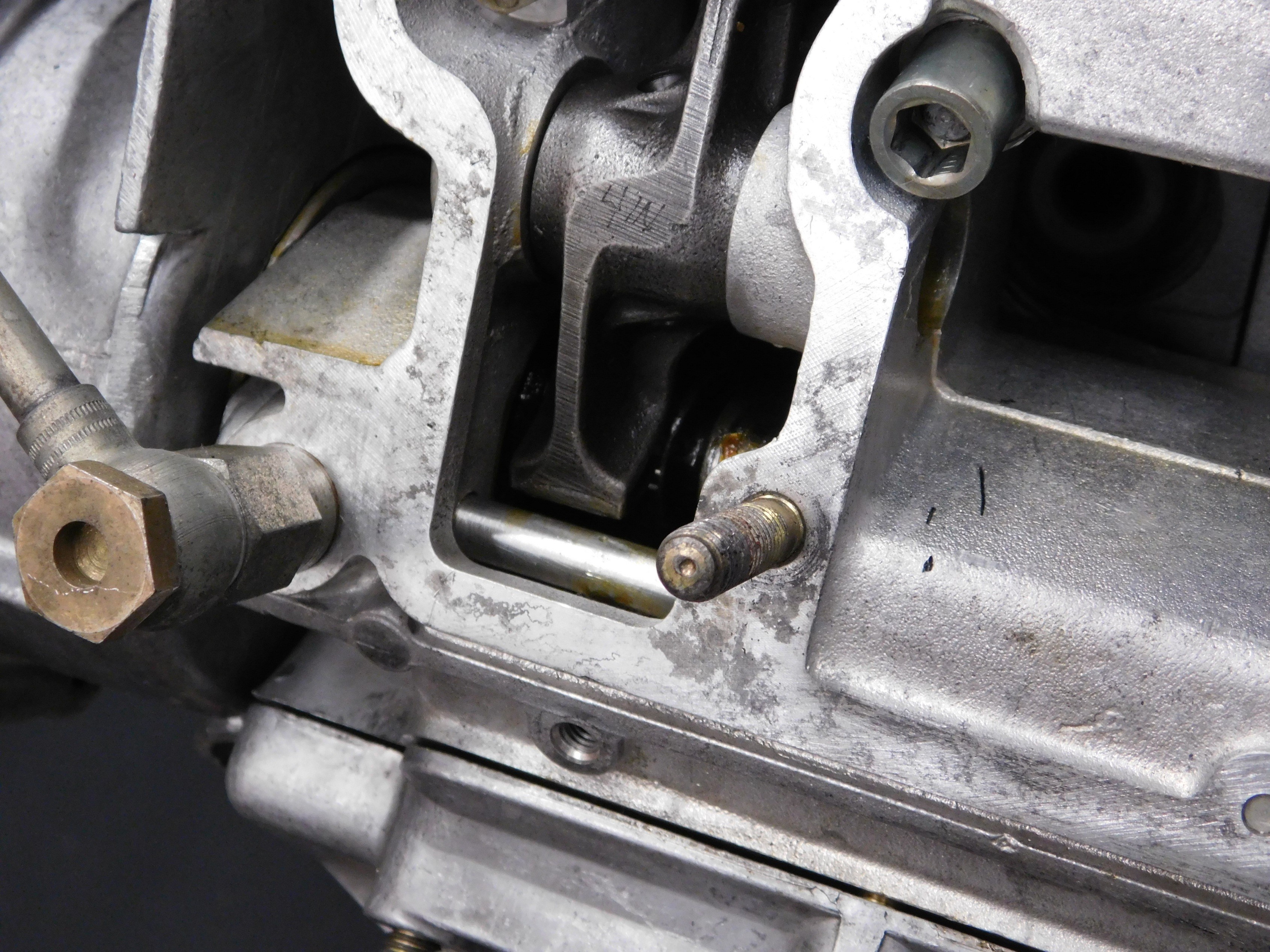
Cylinder 1 intake rocker arm in the up position, valve closed.
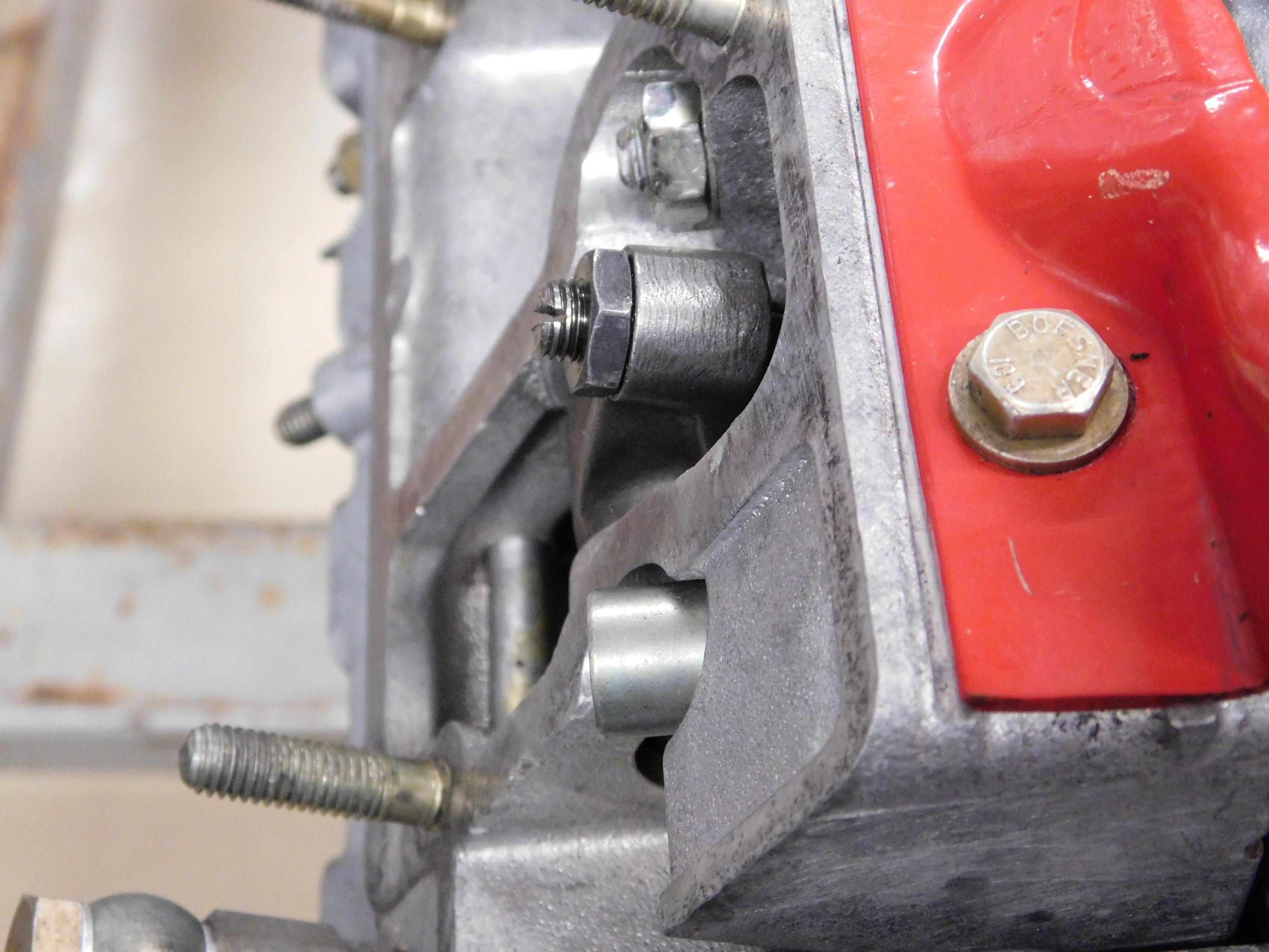
Cylinder 4 intake rocker arm in the down position, valve open.
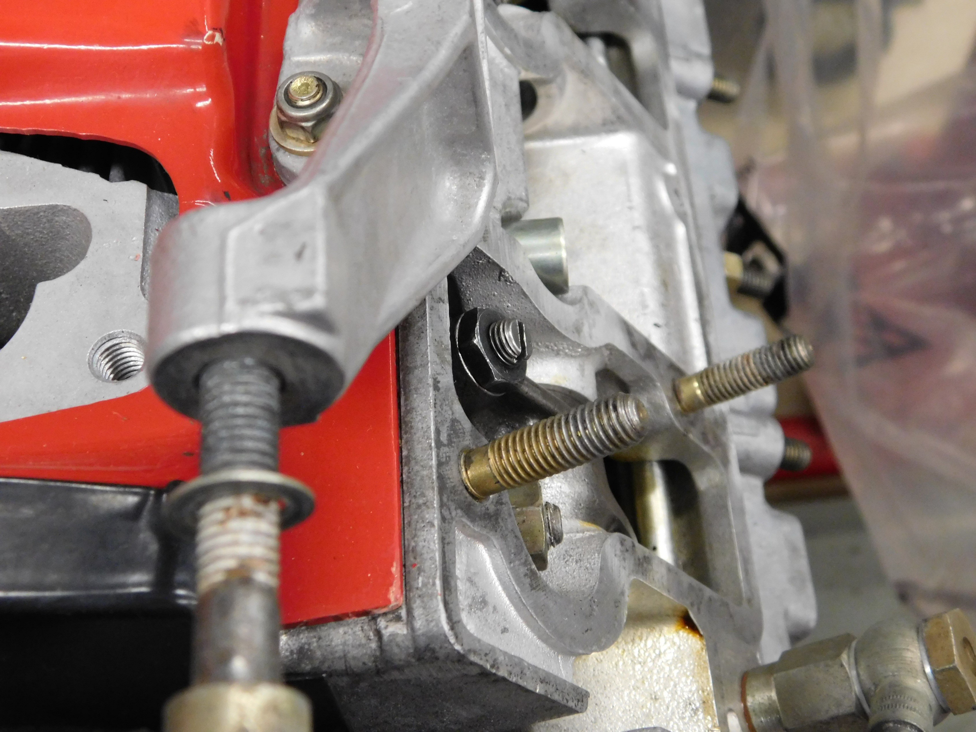
The pictures show how they are opposite to one another.
It is always a very good idea to turn the engine only in a clockwise direction. If you go past your mark, then turn the engine in a clockwise direct and “come around” to your mark again. If you must turn it backwards, turn it past the mark you want, then turn it clockwise to the mark. Go slow just in case the chain tensioner are not fully pumped up so you do not jump a tooth on the timing chain.
Let us assume the engine is cold and you have removed all the parts required to access the valve adjuster, valve covers and any parts attached to the covers, including the spark plugs. On twin plug engines, only one plug per cylinder needs to be removed. Why do you remove the plugs? To make turning the engine over a lot easier. In left hand drive cars, Cylinders 1-2-3 are on the left (drivers side) and 4-5-6 are on the right side (passengers side). Also, do the intake valves and the exhaust valves separately.
We are also assuming the engine is timed correctly and has run and you are checking and adjusting the valve lash. Which mark on the pulley should I use? This is a common question often asked. Forget the marks at this point. Do the adjustment in the firing order. Cylinder number 1 will be the first. How can I tell if cylinder 1 is at TDC? It does not matter where the piston is, what matters is that the rocker arm is on the camshaft base circle or what is also called the heel of the camshaft. This is where looking at cylinder # 4 comes into play. Turn the engine clockwise until you see the rocker arm on cylinder # 4 intake, the top one move and open the valve. Keep turning slowly clockwise until you see the rocker arm open the #4 Intake valve all the way. The rocker arm will deflect downwards into the cam housing and push the #4 intake valve open. If you go over some, that is okay. Now go back and look at the rocker arm on Cylinder 1 Intake. It will be fully in the up position with the intake valve closed, if the cam timing was done correctly. If not, you have bigger issues to take care of, not valve adjustment.
#1 intake rocker arm on the base circle (heel) of the camshaft lobe.
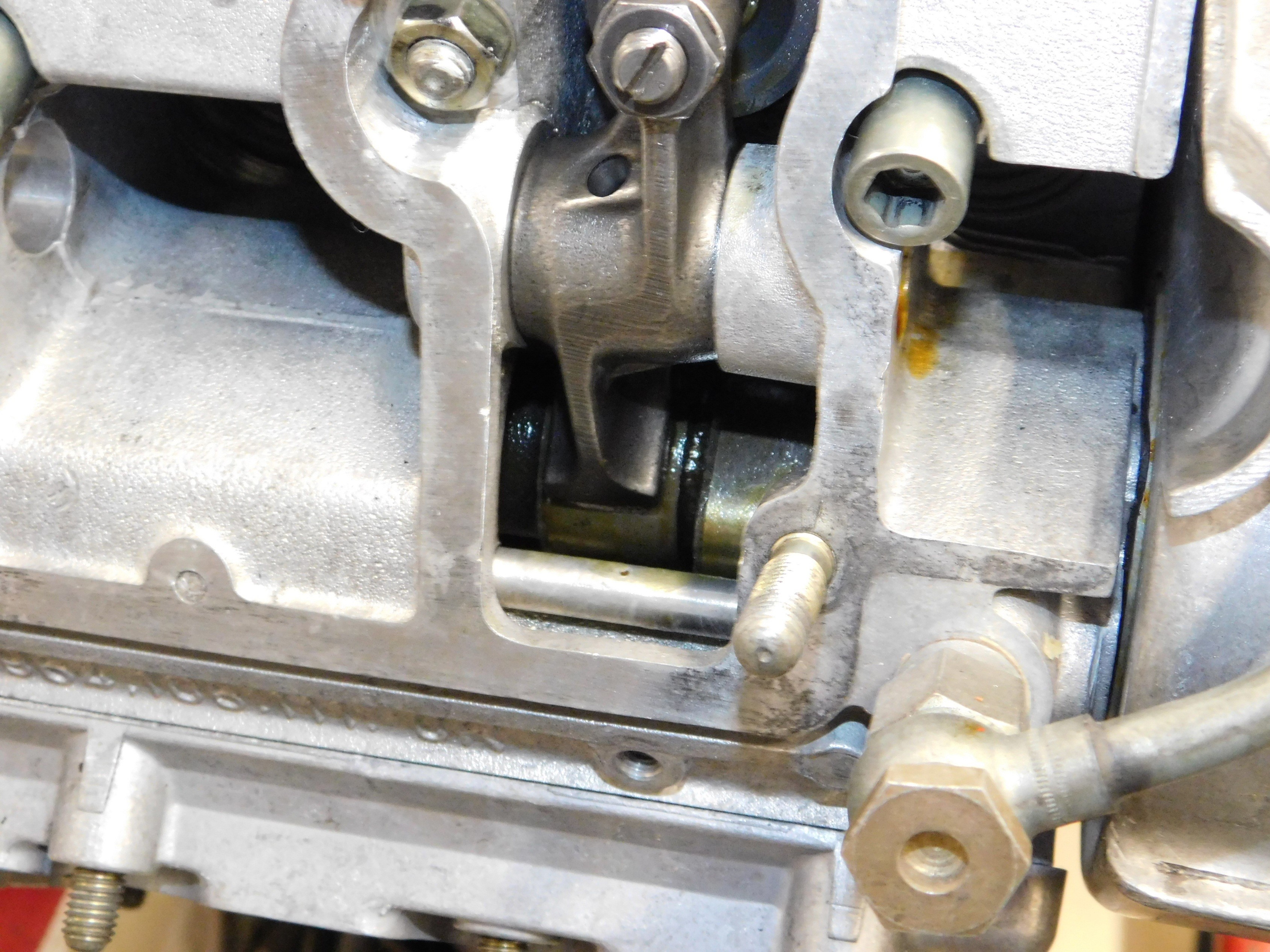
#4 Intake rocker arm on the nose of the camshaft lobe
Hold the intake rocker arm on cylinder 1 and try to move it in and out. There should be some play there. This is the play you are about to measure. If the rocker arm is unloaded, you can usually move it side to side as well. Undo the locking nut insert the correct feeler gauge shim for your engine, turn the adjuster screw until you feel a slight drag on the feeler shim then tighten the lock nut. Check again and repeat until it is correct. Often tightening the lock nut the gap closes. You can leave the feeler shim in-between the parts while you tighten the lock nut. It is a good idea to just give the lock nut a slight turn to seat the nut, then remove the feeler gauge and then tighten the lock nut. Although, there is no torque value often supplied, we typically tighten the lock nut to 180 in/lbs. We do this so the nuts are all tightened the same and by using a socket you limit the chance of rounding over the hex ‘s on the nut.
Now turn the engine clockwise until you see the intake rocker arm on Cylinder # 2 in the fully up position, valve closed. Check the # 5 rocker arm and it should be in the fully downwards position, valve open. Repeat the same adjustment procedure. Do the same for #3 and check the position of the #6 rocker arm. 3 should be all the way up with the valve closed and 6 should be all the down with the valve open. This will require you to turn the engine over more times, but will allow you to do the adjustments on one side of the engine at a time. Now do some math. Looking at the diagram above, you can see that you must turn the engine 240° each time to get the adjacent rocker arm in the correct position to adjust, not 120°. To repeat what I am suggesting, once #1 rocker arm is up, and adjusted, turn the engine 240° and the #2 intake rocker arm will be in the correct position to adjust. If you wish, check the #5 rocker arm on the opposite side and it should be fully down opening the # 5 intake valve. Continue to do the same for the #3 intake valve. Once the #3 valve is done, turn the engine another 240° clockwise and the #4 Intake valve will be in the adjustment position. Again, check where the number 4 rocker arm is. It should be in the fully up position, valve closed and the #1 intake valve fully open, #1 rocker down. If you look at the camshaft and rocker face, you will see the rocker on the heel when the valve is in the adjusting position. Each time you can check where the marks are on the crankshaft pulley. Get the #1 intake rocker arm in the correct position to adjust, make a mark on the pulley then turn the crankshaft so the pulley moves 240°. If this way confuses you, you can always move the crank 120° each time and move from side to side on the engine to do the adjustments.
Once you have completed all the intake valves, do the same for the exhaust valves. Turn the engine clockwise until the #1 exhaust rocker arm is in its fully up position with the exhaust valve closed. Adjust the valve and then turn the engine 240° and do the #2 exhaust valve. All the time if unsure, check the opposite rocker arm. It should be in the opposite position. If the valve you are adjusting has the rocker arm in the up position, the opposite rocker arm will be in the down position.
If you want to do both the Intake and exhaust valves at the same time on each cylinder, you will do the exhaust valve first, exhaust rocker arm fully in the up position, then turn the engine clockwise until the intake rocker arm is in the fully up position. Then continue to turn the engine clockwise approx. 240° and the #2 rocker arm will be ready to adjust. Be careful here as the LSA or lobe separation angle between the intake and exhaust lobes will dictate the amount to turn the engine from adjusting the intake valve and the next exhaust valve. Different cams will have different LSA numbers. This is why I suggest doing the adjustment on the intakes and then go back and do the exhaust. Then you can do 240° each time.
Forget where you were? Do not panic and remember to just keep turning the engine clockwise until the rocker arm of the valve you want to adjust is in the fully up position and the opposite rocker arm is in the fully down position. From there it is 240° each time. It is that easy.